- English
- Español
- Português
- русский
- Français
- 日本語
- Deutsch
- tiếng Việt
- Italiano
- Nederlands
- ภาษาไทย
- Polski
- 한국어
- Svenska
- magyar
- Malay
- বাংলা ভাষার
- Dansk
- Suomi
- हिन्दी
- Pilipino
- Türkçe
- Gaeilge
- العربية
- Indonesia
- Norsk
- تمل
- český
- ελληνικά
- український
- Javanese
- فارسی
- தமிழ்
- తెలుగు
- नेपाली
- Burmese
- български
- ລາວ
- Latine
- Қазақша
- Euskal
- Azərbaycan
- Slovenský jazyk
- Македонски
- Lietuvos
- Eesti Keel
- Română
- Slovenski
- मराठी
- Srpski језик


General Solution Relationship for the Design of Pole Plate Dimensions of Cylindrical Batteries
General Solution Relationship for the Design of Pole Plate Dimensions of Cylindrical Batteries
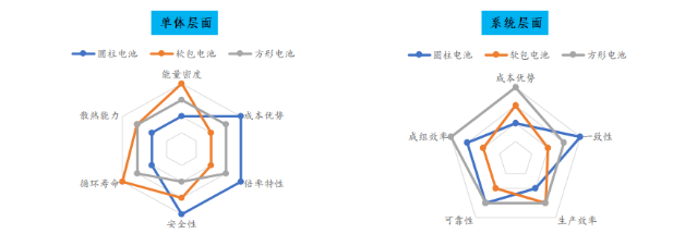
Lithium batteries can be classified into square, soft pack, and cylindrical batteries based on their packaging methods and shapes. Among them, cylindrical batteries have core advantages such as good consistency, high production efficiency, and low manufacturing costs. They have a development history of over 30 years since their inception in 1991. In recent years, with the release of Tesla's all pole ear technology, the application of large cylindrical batteries in the fields of power batteries and energy storage has accelerated, becoming a research hotspot for major lithium battery companies.
Figure 1: Comparison of Performance at the Single and System Levels of Lithium Batteries with Different Shapes
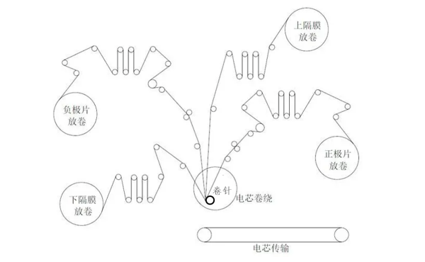
The cylindrical battery shell can be a steel shell, an aluminum shell, or a soft package. Its common feature is that the manufacturing process adopts winding technology, which uses the winding needle as the core and drives the winding needle to rotate to layer and wrap the isolation film and electrode plate together, ultimately forming a relatively uniform cylindrical winding core. As shown in the following figure, a typical winding process is as follows: first, the winding needle clamps the diaphragm for pre winding of the diaphragm, then the negative electrode is inserted between two layers of isolation film for pre winding of the negative electrode, and then the positive electrode is inserted for high-speed winding. After the winding is completed, the cutting mechanism cuts the electrode and diaphragm, and finally, a layer of adhesive tape is applied at the end to fix the shape.
Figure 2: Schematic diagram of winding process
The control of the core diameter after winding is crucial. If the diameter is too large, it cannot be assembled, and if the diameter is too small, there is a waste of space. Therefore, accurate design of the core diameter is crucial. Fortunately, cylindrical batteries are relatively regular geometries, and the circumference of each layer of electrode and diaphragm can be calculated by approximating a circle. Finally, the total length of the electrode can be accumulated to obtain the capacity design. The accumulated values of needle diameter, electrode layer number, and diaphragm layer number are the diameter of the wound core. It should be noted that the core elements of lithium-ion battery design are capacity design and size design. In addition, through theoretical calculations, we can also design the pole ear at any position of the coil core, not limited to the head, tail, or center, and also cover the design methods of multi pole ear and all pole ear for cylindrical batteries.
In order to explore the issues of electrode length and core diameter, we first need to study three processes: infinite pre winding of the isolation film, infinite pre winding of the negative electrode, and infinite winding of the positive electrode. Assuming the diameter of the coil needle is p, the thickness of the isolation film is s, the thickness of the negative electrode is a, and the thickness of the positive electrode is c, all in millimeters.
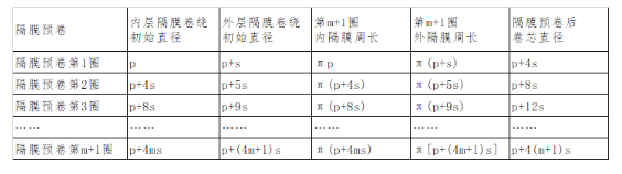
- Infinite pre winding process of isolation membrane
During the pre winding process of the diaphragm, two layers of diaphragms are wound simultaneously, so the diameter of the outer diaphragm during the winding process is always one more layer of diaphragm thickness (+1s) than the inner diaphragm. The initial diameter of the inner diaphragm winding is the end diameter of the previous winding, and for each pre winding of the diaphragm, the core diameter increases by four layers of diaphragm thickness (+4s).
Appendix 1: Diameter variation law of infinite pre winding process of isolation membrane
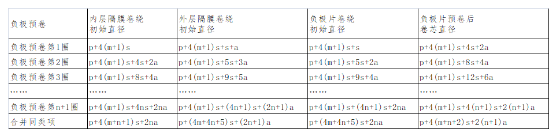
- Infinite pre winding process of negative electrode
During the pre winding process of the negative electrode, due to the addition of a layer of negative electrode, the diameter of the outer diaphragm during the winding process is always one layer more than the thickness of the inner diaphragm and one layer of negative electrode (+1s+1a), and the initial diameter of the inner diaphragm winding is always equal to the end diameter of the previous circle. At this time, for each pre winding of the negative electrode, the core diameter increases by four layers of diaphragm and two layers of negative electrode thickness (+4s+2a).
Appendix 2: Diameter variation law of the infinite pre winding process of the negative electrode plate
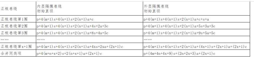
Infinite winding process of positive electrode plate
During the winding process of the positive electrode, due to the addition of a new layer of positive electrode, the initial diameter of the positive electrode is always equal to the end diameter of the previous circle, while the initial diameter of the inner diaphragm winding becomes the end diameter of the previous circle plus the thickness of one layer of positive electrode (+1c). However, during the winding process of the outer diaphragm, the diameter is always only one layer more than the thickness of the inner diaphragm and one layer of negative electrode (+1s+1a). At this time, the negative electrode is pre wound for each circle, The diameter of the coil core increases by 4 layers of diaphragm, 2 layers of negative electrode, and 2 layers of positive electrode thickness (+4s+2s+2a).
Appendix 3: Diameter variation law of the positive electrode during infinite winding process
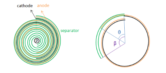
Above, through the analysis of the infinite winding process of the diaphragm and electrode plate, we have obtained the variation pattern of the core diameter and electrode plate length. This layer by layer analytical calculation method is conducive to accurately arranging the position of the electrode ears (including single pole ears, multipole ears, and full pole ears), but the winding process has not ended yet. At this point, the positive electrode plate, negative electrode plate, and isolation film are in a flush state. The basic principle of battery design is to require the isolation film to completely cover the negative electrode plate And the negative electrode should also completely cover the positive electrode.
Figure 3: Schematic diagram of cylindrical battery coil structure and closing process
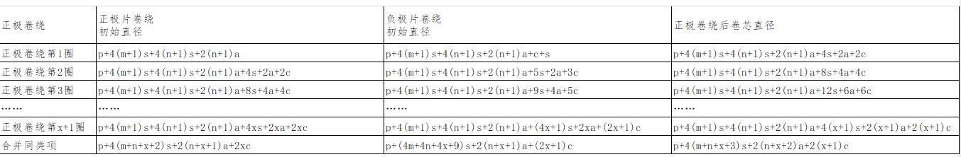
Therefore, it is necessary to further explore the issue of winding the core negative electrode and isolation film. Obviously, since the positive electrode has already been wound, and before this, the initial diameter of the positive electrode is always equal to the end diameter of the previous circle, the initial diameter of the inner layer diaphragm replaces the end diameter of the previous circle. On this basis, the initial diameter of the negative electrode increases the thickness of one layer of diaphragm (+1s), Increase the initial diameter of the outer diaphragm by one more layer of negative electrode thickness (+1s+1a).
Appendix 4: Variations in diameter and length of electrode and diaphragm during the winding process of cylindrical batteries
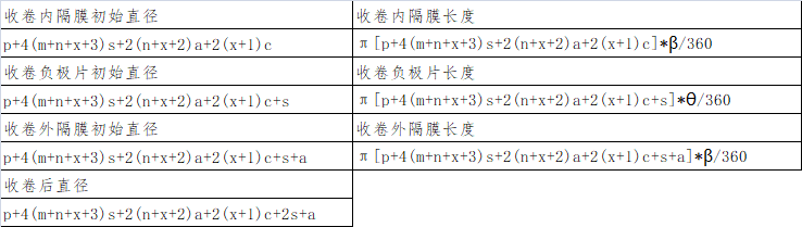
So far, we have obtained the mathematical expression of the length of positive plate, negative plate and isolation film under any number of winding cycles. Suppose that the diaphragm is pre wound m+1 cycles, the negative plate is pre wound n+1 cycles, the positive plate is wound x+1 cycles, and the Central angle of the negative plate is θ °, the Central angle of isolation film winding is β °, then there is the following relationship:
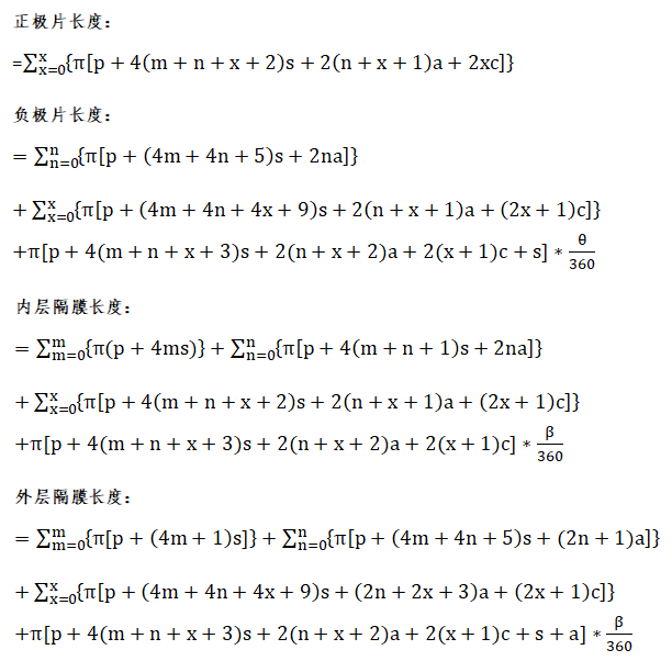
The determination of the number of electrode and diaphragm layers not only determines the length of the electrode and diaphragm, which in turn affects the capacity design, but also determines the final diameter of the coil core, greatly reducing the assembly risk of the coil core. Although we obtained the diameter of the core after winding, we did not consider the thickness of the pole ear and the ending adhesive paper. Assuming that the thickness of the positive ear is tabc, the thickness of the negative ear is taba, and the ending adhesive is 1 circle and the overlapping area avoids the position of the pole ear, with a thickness of g. Therefore, the final diameter of the core is:
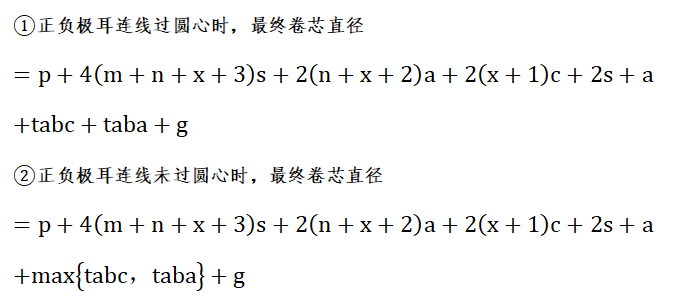
The above formula is the general solution relationship for the design of cylindrical battery electrode plates. It determines the problem of electrode plate length, diaphragm length, and coil core diameter, and quantitatively describes the relationship between them, greatly improving design accuracy and having great practical application value.
Finally, what we need to solve is the problem of arranging the pole ears. Usually, there are one or two pole ears or even three pole ears on one pole piece, which is a small number of pole ears. The tab lead is welded to the surface of the pole piece. Although it may affect the accuracy of the pole piece length design to some extent (without affecting the diameter), the tab lead is usually narrow and has little impact, Therefore, the general solution formula for the size design of cylindrical batteries proposed in this article ignores this issue.
Figure 4: Layout of Positive and Negative Ear Positions
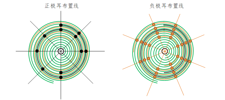
The above diagram is a schematic diagram of the placement of pole lugs. Based on the previously proposed general relationship of pole piece size, we can clearly understand the length and diameter changes of each layer of pole pieces during the winding process. Therefore, when arranging pole lugs, the positive and negative lugs can be accurately arranged at the target position of the pole piece in the case of a single pole lug, while for the case of multiple or full pole lugs, it is usually required to align multiple layers of pole lugs, On this basis, we only need to deviate from the fixed angle of each layer of lug, so as to obtain the arrangement position of each layer of lug. As the diameter of the winding core gradually increases during the winding process, the overall arrangement distance of the lug is approximately changed by the arithmetic progression with π (4s+2a+2c) as the tolerance.
In order to further investigate the influence of thickness fluctuations of electrode plates and diaphragms on the diameter and length of the coil core, taking the 4680 large cylindrical full electrode ear cell as an example, assuming that the coil needle diameter is 1mm, the thickness of the closing tape is 16um, the thickness of the isolation film is 10um, the cold pressing thickness of the positive electrode plate is 171um, the thickness during winding is 174um, the cold pressing thickness of the negative electrode plate is 249um, the thickness during winding is 255um, and both the diaphragm and negative electrode plates are pre rolled for 2 turns. The calculation shows that the positive electrode plate is wound for 47 turns, with a length of 3371.6mm, The negative electrode is wound 49.5 times, with a length of 3449.7mm and a diameter of 44.69mm after winding.
Figure 5: The Influence of Thickness Fluctuation of Pole and Diaphragm on the Core Diameter and Pole Length
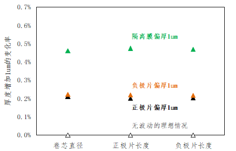
From the above figure, it can be intuitively seen that the fluctuation of the thickness of the pole piece and diaphragm has a certain impact on the diameter and length of the coil core. When the thickness of the pole piece deviates by 1um, the diameter and length of the coil core increase by about 0.2%, while when the thickness of the diaphragm deviates by 1um, the diameter and length of the coil core increase by about 0.5%. Therefore, in order to control the consistency of the diameter of the coil core, the fluctuation of the pole piece and diaphragm should be minimized as much as possible, And it is also necessary to collect the relationship between the rebound of the electrode plate and time between cold pressing and winding, in order to assist in the cell design process.
Summary
1. Capacity design and diameter design are the lowest level design logic for cylindrical lithium batteries. The key to capacity design lies in the length of the electrode, while the key to diameter design lies in the analysis of the number of layers.
2. The arrangement of pole ear positions is also crucial. For multi pole ear or full pole ear structures, pole ear alignment can be used as a criterion for evaluating the design ability and process control ability of the battery cell. The method of layer by layer analysis can better meet the requirements of pole ear position arrangement and alignment.