- English
- Español
- Português
- русский
- Français
- 日本語
- Deutsch
- tiếng Việt
- Italiano
- Nederlands
- ภาษาไทย
- Polski
- 한국어
- Svenska
- magyar
- Malay
- বাংলা ভাষার
- Dansk
- Suomi
- हिन्दी
- Pilipino
- Türkçe
- Gaeilge
- العربية
- Indonesia
- Norsk
- تمل
- český
- ελληνικά
- український
- Javanese
- فارسی
- தமிழ்
- తెలుగు
- नेपाली
- Burmese
- български
- ລາວ
- Latine
- Қазақша
- Euskal
- Azərbaycan
- Slovenský jazyk
- Македонски
- Lietuvos
- Eesti Keel
- Română
- Slovenski
- मराठी
- Srpski језик


Summary of causes of bulging in soft pack lithium-ion batteries
Summary of causes of bulging in soft pack lithium-ion batteries
There are many reasons for the swelling of soft pack lithium-ion batteries. Based on experimental research and development experience, the author divides the causes of lithium battery bulging into three categories: firstly, the increase in thickness caused by the expansion of the battery electrode during cycling; The second is the swelling caused by the oxidation and decomposition of electrolyte to produce gas. The third is the bulging caused by process defects such as moisture and damaged corners due to lax battery packaging. In different battery systems, the dominant factor for changes in battery thickness is different. For example, in lithium titanate negative electrode systems, the main factor for bulging is gas drum; In the graphite negative electrode system, the thickness of the electrode plate and gas production both promote the swelling of the battery.
1、 Change in electrode plate thickness
Discussion on the Factors and Mechanisms Influencing the Expansion of Graphite Negative Electrode
The increase in cell thickness during the charging process of lithium-ion batteries is mainly attributed to the expansion of the negative electrode. The expansion rate of the positive electrode is only 2-4%, and the negative electrode is usually composed of graphite, adhesive, and conductive carbon. The expansion rate of the graphite material itself reaches~10%, and the main influencing factors of the change in graphite negative electrode expansion rate include: SEI film formation, state of charge (SOC), process parameters, and other influencing factors.
(1) During the first charging and discharging process of lithium-ion batteries formed by SEI film, the electrolyte undergoes a reduction reaction at the solid-liquid interface of graphite particles, forming a passivation layer (SEI film) covering the surface of the electrode material. The formation of SEI film significantly increases the anode thickness, and due to the formation of SEI film, the cell thickness increases by about 4%. From the perspective of long-term cycling process, depending on the physical structure and specific surface area of different graphite, the cycling process will result in the dissolution of SEI and the dynamic process of new SEI production, such as flake graphite having a higher expansion rate than spherical graphite.
(2) During the cycling process of the charged state battery cell, the volume expansion of the graphite anode exhibits a good periodic functional relationship with the SOC of the battery cell. That is, as lithium ions continue to embed in the graphite (with an increase in SOC of the battery cell), the volume gradually expands. As lithium ions detach from the graphite anode, the SOC of the battery cell gradually decreases, and the corresponding volume of the graphite anode gradually decreases.
(3) From the perspective of process parameters, the compaction density has a significant impact on the graphite anode. During the cold pressing process of the electrode, a large compressive stress is generated in the graphite anode film layer, which is difficult to fully release in subsequent high-temperature baking and other processes of the electrode. When the battery cell undergoes cyclic charging and discharging, due to the combined effects of multiple factors such as lithium ion insertion and detachment, electrolyte swelling on the adhesive, the membrane stress is released during the cycling process, and the expansion rate increases. On the other hand, the compaction density determines the pore capacity of the anode film layer. The pore capacity in the film layer is large, which can effectively absorb the volume of the electrode expansion. The pore capacity is small, and when the electrode expansion occurs, there is not enough space to absorb the volume generated by the expansion. At this time, the expansion can only expand towards the outside of the film layer, manifested as the volume expansion of the anode film.
(4) Other factors such as the bonding strength of the adhesive (adhesive, graphite particles, conductive carbon, and the bonding strength of the interface between the collector and the fluid), charge discharge rate, the swelling ability of the adhesive and the electrolyte, the shape and stacking density of graphite particles, and the increase in electrode volume caused by the failure of the adhesive during the cycling process all have a certain degree of impact on the anode expansion.
For expansion rate calculation, use anime method to measure the size of anode plate in X and Y directions, use micrometer to measure the thickness in Z direction, and measure separately after the stamping plate and the electric core are fully charged.

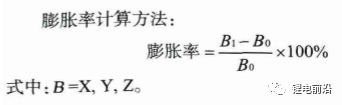
Figure 1 Schematic diagram of anode plate measurement
The Influence of Compaction Density and Coating Quality on Negative Electrode Expansion
Using compaction density and coating quality as factors, three different levels were taken for a full factor orthogonal experimental design (as shown in Table 1), with other conditions being the same for each group.

As shown in Figures 2 (a) and (b), after the battery cell is fully charged, the expansion rate of the anode sheet in the X/Y/Z direction increases with the increase of compaction density. When the compaction density increases from 1.5g/cm3 to 1.7g/cm3, the expansion rate in the X/Y direction increases from 0.7% to 1.3%, and the expansion rate in the Z direction increases from 13% to 18%. From Figure 2 (a), it can be seen that under different compaction densities, the expansion rate in the X direction is greater than that in the Y direction. The main reason for this phenomenon is caused by the cold pressing process of the polar plate. During the cold pressing process, when the polar plate passes through the pressing roller, according to the law of minimum resistance, when the material is subjected to external forces, the material particles will flow along the direction of minimum resistance
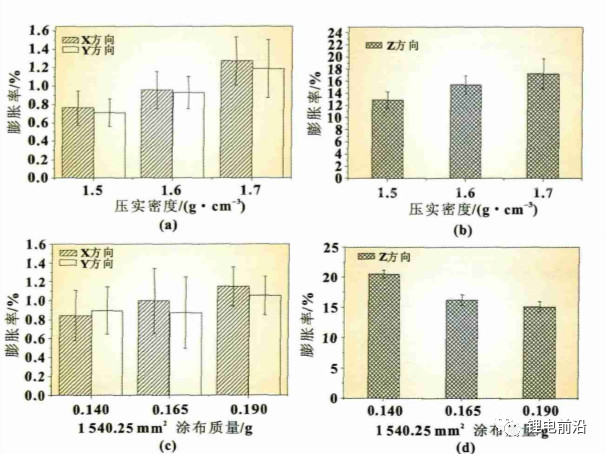
Figure 2 Expansion rate of anodes in different directions
When the anode plate is cold pressed, the direction with the lowest resistance is in the MD direction (Y direction of the electrode plate, as shown in Figure 3). The stress is easier to release in the MD direction, while the TD direction (X direction of the electrode plate) has a higher resistance, making it difficult to release the stress during the rolling process. The stress in the TD direction is greater than that in the MD direction. Therefore, after the electrode sheet is fully charged, the expansion rate in the X direction is greater than that in the Y direction. On the other hand, the compaction density increases, and the pore capacity of the electrode sheet decreases (as shown in Figure 4). When charging, there is not enough space inside the anode film layer to absorb the volume of graphite expansion, and the external manifestation is that the electrode sheet expands in the X, Y, and Z directions as a whole. From Figures 2 (c) and (d), it can be seen that the coating quality increased from 0.140g/1540.25mm2 to 0.190g/1540.25mm2, the expansion rate in the X direction increased from 0.84% to 1.15%, and the expansion rate in the Y direction increased from 0.89% to 1.05%. The trend of the expansion rate in the Z direction is opposite to that in the X/Y direction, showing a downward trend, from 16.02% to 13.77%. The expansion of graphite anode exhibits a fluctuating pattern in the X, Y, and Z directions, and the change in coating quality is mainly reflected in the significant change in film thickness. The above anode variation pattern is consistent with the literature results, that is, the smaller the ratio of collector thickness to film thickness, the greater the stress in the collector.
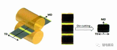

Figure 4 Changes in Void Fraction under Different Compaction Densities
The effect of copper foil thickness on negative electrode expansion
Select two influencing factors, copper foil thickness and coating quality, with copper foil thickness levels of 6 and 8, respectively μ m. The anode coating masses were 0.140g/1, 540.25mm2, and 0.190g/1, 540.25mm2, respectively. The compaction density was 1.6g/cm3, and other conditions were the same for each group of experiments. The experimental results are shown in Figure 5. From Figures 5 (a) and (c), it can be seen that under two different coating qualities, in the X/Y direction 8 μ The expansion rate of m copper foil anode sheet is less than 6 μ m. The increase in thickness of copper foil results in an increase in its elastic modulus (see Figure 6), which enhances its resistance to deformation and enhances its constraint on anode expansion, resulting in a decrease in expansion rate. According to literature, with the same coating quality, as the thickness of copper foil increases, the ratio of collector thickness to film thickness increases, the stress in the collector decreases, and the expansion rate of the electrode decreases. In the Z direction, the trend of expansion rate change is completely opposite. From Figure 5 (b), it can be seen that as the thickness of the copper foil increases, the expansion rate increases; From the comparison of Figures 5 (b) and (d), it can be seen that when the coating quality increases from 0.140g/1 and 540.25mm2 to 0.190g/1540.25mm2, the thickness of the copper foil increases and the expansion rate decreases. Increasing the thickness of copper foil, although beneficial for reducing its own stress (high strength), will increase the stress in the film layer, leading to an increase in Z-direction expansion rate, as shown in Figure 5 (b); As the coating quality increases, although thick copper foil has a promoting effect on the stress increase of the film layer, it also enhances the binding capacity of the film layer. At this time, the binding force becomes more obvious and the Z-direction expansion rate decreases.

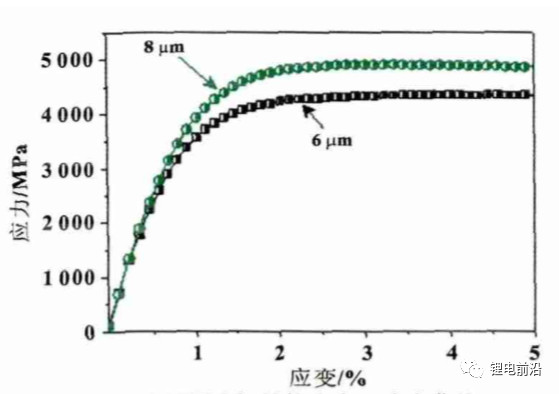
Figure 6 stress-strain curves of copper foil with different thicknesses
The effect of graphite type on negative electrode expansion
Five different types of graphite were used for the experiment (see Table 2), with a coating mass of 0.165g/1540.25mm2, a compaction density of 1.6g/cm3, and a copper foil thickness of 8 μ m. Other conditions are the same, and the experimental results are shown in Figure 7. From Figure 7 (a), it can be seen that there are significant differences in the expansion rates of different graphites in the X/Y direction, with a minimum of 0.27% and a maximum of 1.14%. The expansion rates in the Z direction are 15.44% and 17.47%, respectively. Those with large expansion in the X/Y direction have small expansion in the Z direction, which is consistent with the results analyzed in Section 2.2. The cells using A-1 graphite showed severe deformation with a deformation rate of 20%, while the other groups of cells did not show deformation, indicating that the size of X/Y expansion rate has a significant impact on cell deformation.
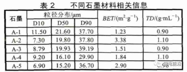
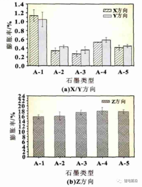
Figure 7 Different graphite expansion rates
Conclusion
(1) Increasing the compaction density increases the expansion rate of the anode sheet in the X/Y and Z directions during the full filling process, and the expansion rate in the X direction is greater than that in the Y direction (the X direction is the roller axis direction during the cold pressing process of the anode sheet, and the Y direction is the machine belt direction).
(2) By increasing the coating quality, the expansion rate in the X/Y direction tends to increase, while the expansion rate in the Z direction decreases; Increasing the coating quality will lead to an increase in tensile stress in the fluid collection.
(3) Improving the strength of the current collector can suppress the expansion of the anode in the X/Y direction.
(4) Different types of graphite have significant differences in expansion rates in the X/Y and Z directions, with the expansion size in the X/Y direction having a significant impact on cell deformation.
2、 Bulging caused by battery gas production
The internal gas production of batteries is another important reason for battery bulging, whether it is during room temperature cycling, high-temperature cycling, or high-temperature storage, it will produce varying degrees of bulging gas production. During the initial charging and discharging process of the battery, a SEI (Solid Electrolyte Interface) film will form on the electrode surface. The formation of negative SEI film mainly comes from the reduction and decomposition of EC (Ethylene Carbonate). Along with the generation of alkyl lithium and Li2CO3, a large amount of CO and C2H4 are generated. DMC (Dimethyl Carbonate) and EMC (Ethyl Methyl Carbonate) in solvents also form RLiCO3 and ROLi during the film forming process, accompanied by the production of gases such as CH4, C2H6, and C3H8, as well as CO gases. In PC (Propylene carbonate) based electrolytes, gas production is relatively high, mainly C3H8 gas generated by PC reduction. Lithium iron phosphate soft pack batteries experience the most severe inflation after charging at 0.1C during the first cycle. As can be seen from the above, the formation of SEI is accompanied by the production of a large amount of gas, which is an inevitable process. The presence of H2O in impurities will cause the P-F bond in LiPF6 to become unstable, generating HF, which will lead to the instability of this battery system and the generation of gas. The presence of excessive H2O will consume Li+and generate LiOH, LiO2, and H2, leading to the production of gases. During storage and long-term charging and discharging processes, gas can also be generated. For sealed lithium-ion batteries, the presence of a large amount of gas can cause the battery to expand, thereby affecting its performance and shortening its service life. The main reasons for gas generation during battery storage are as follows: (1) The presence of H2O in the battery system can lead to the generation of HF, causing damage to SEI. The O2 in the system may cause oxidation of the electrolyte, leading to the generation of a large amount of CO2; (2) If the SEI film formed during the first formation is unstable, it will cause damage to the SEI film during the storage stage, and the re repair of the SEI film will release gases mainly composed of hydrocarbons. During the long-term charging and discharging cycle of the battery, the crystal structure of the positive material changes, the uneven point potential on the electrode surface and other factors cause some point potentials to be too high, the stability of the electrolyte on the electrode surface decreases, the constant thickening of the facial mask on the electrode surface makes the electrode interface resistance increase, further improving the reaction potential, causing the decomposition of the electrolyte on the electrode surface to produce gas, and the positive material may also release gas.

Figure 8 Gas composition of Li4Ti5O12/LiMn2O4 battery after 5 months of cycling at 30, 45, and 60 ℃
The electrolyte system commonly used for lithium-ion batteries is LiPF6/EC: EMC, where LiPF6 has the following balance in the electrolyte

PF5 is a strong acid that easily causes the decomposition of carbonates, and the amount of PF5 increases with increasing temperature. PF5 helps to decompose the electrolyte, producing CO2, CO, and CxHy gases. The calculation also indicates that the decomposition of EC produces CO and CO2 gases. C2H4 and C3H6 are generated by the oxidation-reduction reaction of C2H6 and C3H8 with Ti4+, respectively, while Ti4+is reduced to Ti3+. According to relevant research, the generation of H2 comes from trace amounts of water in the electrolyte, but the water content in the electrolyte is generally 20 × Around 10-6, for H2 gas production. Wu Kai's experiment at Shanghai Jiao Tong University selected graphite/NCM111 as the battery with a low contribution, and concluded that the source of H2 is the decomposition of carbonate under high voltage.
3、 Abnormal process leading to gas generation and expansion
1. Poor packaging has significantly reduced the proportion of inflated battery cells caused by poor packaging. The reasons for poor top sealing, side sealing and degassing three side packaging have been introduced previously. Bad packaging on either side will lead to the battery cell, which is mainly represented by top sealing and degassing. Top sealing is mainly due to poor sealing at the tab position, and degassing is mainly due to layering (including separation of PP from Al due to electrolyte and gel). Poor packaging causes moisture in the air to enter the interior of the battery cell, causing electrolyte to decompose and produce gas.
2. The surface of the pocket is damaged, and the battery cell is abnormally damaged or artificially damaged during the pulling process, resulting in pocket damage (such as pinholes) and allowing water to enter the interior of the battery cell.
3. Corner damage: Due to the special deformation of aluminum at the folded corner, the shaking of the air bag can distort the corner and cause Al damage (the larger the battery cell, the larger the air bag, the easier it is to be damaged), losing its barrier effect on water. Wrinkle glue or hot melt glue can be added to the corners to alleviate the problem. And it is prohibited to move the battery cells with air bags in each process after the top sealing, and more attention should be paid to the operation method to prevent the oscillation of the battery cell pool on the aging board.
4. The water content inside the battery cell exceeds the standard. Once the water content exceeds the standard, the electrolyte will fail and produce gas after formation or degassing. The main reasons for the excessive water content inside the battery are: the excessive water content in the electrolyte, the excessive water content in the bare cell after Baking, and the excessive humidity in the drying room. If it is suspected that the excessive water content may cause bloating, a retrospective inspection of the process can be carried out.
5. The formation process is abnormal, and an incorrect formation process can cause the battery cell to inflate.
6. The SEI film is unstable, and the emission function of the battery cell is slightly inflated during the capacity test charging and discharging process.
7. Overcharging or discharging: Due to abnormalities in the process, machine, or protective board, the battery cells may be overcharged or discharged excessively, resulting in severe air bubbles in the battery cells.
8. Short circuit: Due to operational errors, the two tabs of the charged battery cell come into contact and experience a short circuit. The battery cell will experience gas explosion and the voltage will rapidly decrease, causing the tabs to burn black.
9. Internal short circuit: The internal short circuit between the positive and negative poles of the battery cell causes rapid discharge and heating of the battery cell, as well as severe gas puffing. There are many reasons for internal short circuits: design issues; Shrinkage, curling, or damage of the isolation film; Bi cell misalignment; Burrs piercing the isolation membrane; Excessive fixture pressure; Excessive squeezing of the edge ironing machine, etc. For example, in the past, due to insufficient width, the edge ironing machine excessively squeezed the battery cell entity, resulting in short circuit and bloating of the cathode and anode.
10. Corrosion: The battery cell undergoes corrosion, and the aluminum layer is consumed by the reaction, losing its barrier to water and causing gas expansion.
11. Abnormal vacuum pumping, caused by system or machine reasons. Degassing is not thorough; The thermal radiation zone of Vacuum Sealing is too large, causing the Degassing suction bayonet to not effectively pierce the Pocket bag, resulting in unclean suction.
Measures to suppress abnormal gas production
4. Suppressing abnormal gas production requires starting from both material design and manufacturing processes.
Firstly, it is necessary to design and optimize the material and electrolyte system to ensure the formation of a dense and stable SEI film, improve the stability of the positive electrode material, and suppress the occurrence of abnormal gas production.
For the treatment of electrolytes, the method of adding a small amount of film-forming additives is often used to make the SEI film more uniform and dense, reducing the detachment of the SEI film during use and gas production during regeneration, which leads to battery bulging. Relevant research has been reported and applied in practice, such as Cheng Su from Harbin Institute of Technology, who reported that the use of film-forming additive VC can reduce battery bulging. However, research has mostly focused on single component additives, with limited effectiveness. Cao Changhe and others from East China University of Science and Technology used VC and PS composite as a new electrolyte film-forming additive, achieving good results. The gas production of the battery was significantly reduced during high-temperature storage and cycling. Research has shown that the SEI membrane components formed by EC and VC are linear alkyl lithium carbonate. At high temperatures, alkyl lithium carbonate attached to LiC is unstable and decomposes into gases such as CO2, resulting in battery swelling. The SEI film formed by PS is lithium alkyl sulfonate. Although the film has defects, it has a certain two-dimensional structure and is still relatively stable when attached to LiC at high temperatures. When VC and PS are used in combination, PS forms a defective two-dimensional structure on the negative electrode surface at low voltage. As the voltage increases, VC forms a linear structure of alkyl lithium carbonate on the negative electrode surface. Alkyl lithium carbonate is filled in the defects of the two-dimensional structure, forming a stable SEI film with a network structure attached to LiC. The SEI membrane with this structure greatly improves its stability and can effectively suppress gas production caused by membrane decomposition.