- English
- Español
- Português
- русский
- Français
- 日本語
- Deutsch
- tiếng Việt
- Italiano
- Nederlands
- ภาษาไทย
- Polski
- 한국어
- Svenska
- magyar
- Malay
- বাংলা ভাষার
- Dansk
- Suomi
- हिन्दी
- Pilipino
- Türkçe
- Gaeilge
- العربية
- Indonesia
- Norsk
- تمل
- český
- ελληνικά
- український
- Javanese
- فارسی
- தமிழ்
- తెలుగు
- नेपाली
- Burmese
- български
- ລາວ
- Latine
- Қазақша
- Euskal
- Azərbaycan
- Slovenský jazyk
- Македонски
- Lietuvos
- Eesti Keel
- Română
- Slovenski
- मराठी
- Srpski језик


Coating process and defects of lithium batteries
Coating process and defects of lithium batteries
01
The influence of coating process on the performance of lithium batteries
Polar coating generally refers to a process of evenly coating a stirred slurry onto a current collector and drying the organic solvents in the slurry. The coating effect has a significant impact on battery capacity, internal resistance, cycle life, and safety, ensuring even coating of the electrode. The selection of coating methods and control parameters have a significant impact on the performance of lithium-ion batteries, mainly manifested in:
1) Drying temperature control for coating: If the drying temperature is too low during coating, it cannot guarantee complete drying of the electrode. If the temperature is too high, it may be due to the rapid evaporation of organic solvents inside the electrode, resulting in cracking, peeling, and other phenomena on the surface coating of the electrode;
2) Coating surface density: If the coating surface density is too small, the battery capacity may not reach the nominal capacity. If the coating surface density is too high, it is easy to cause waste of ingredients. In severe cases, if there is excessive positive electrode capacity, lithium dendrites will form due to lithium precipitation, piercing the battery separator and causing a short circuit, posing a safety hazard;
3) Coating size: If the coating size is too small or too large, it may cause the positive electrode inside the battery to not be completely covered by the negative electrode. During the charging process, lithium ions are embedded from the positive electrode and move into the electrolyte that is not completely covered by the negative electrode. The actual capacity of the positive electrode cannot be efficiently utilized. In severe cases, lithium dendrites may form inside the battery, which can easily puncture the separator and cause internal circuit damage;
4) Coating thickness: If the coating thickness is too thin or too thick, it will affect the subsequent electrode rolling process and cannot guarantee the consistency of battery electrode performance.
In addition, electrode coating is of great significance for the safety of batteries. Before coating, 5S work should be done to ensure that no particles, debris, dust, etc. are mixed into the electrode during the coating process. If any debris is mixed, it will cause a micro short circuit inside the battery, which can lead to fire and explosion in severe cases.
02
Selection of coating equipment and coating process
The general coating process includes: uncoiling → splicing → pulling → tension control → coating → drying → correction → tension control → correction → winding, and other processes. The coating process is complex, and there are also many factors that affect the coating effect, such as the manufacturing accuracy of the coating equipment, the smoothness of equipment operation, the control of dynamic tension during the coating process, the size of air flow during the drying process, and the temperature control curve. Therefore, choosing a suitable coating process is extremely important.
The general selection of coating method needs to consider the following aspects, including: the number of layers to be coated, the thickness of the wet coating, the rheological properties of the coating liquid, the required coating accuracy, the coating support or substrate, and the coating speed.
In addition to the above factors, it is also necessary to consider the specific situation and characteristics of the electrode coating. The characteristics of lithium-ion battery electrode coating are: ① double-sided single-layer coating; ② The wet coating of the slurry is relatively thick (100-300 μ m) ③ The slurry is a non Newtonian high viscosity fluid; ④ The precision requirement for polar film coating is high, similar to that of film coating; ⑤ Coating support body with a thickness of 10-20 μ Aluminum foil and copper foil of m; ⑥ Compared to the film coating speed, the polar film coating speed is not high. Taking into account the above factors, general laboratory equipment often uses scraper type, consumer lithium-ion batteries often use roller coating transfer type, and power batteries often use narrow slot extrusion method.
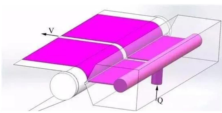
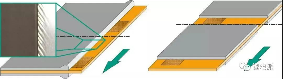
Roller coating transfer type: The coating roller rotates to drive the slurry, adjust the slurry transfer amount through the gap between the comma scraper, and use the rotation of the back roller and coating roller to transfer the slurry to the substrate. The process is shown in Figure 2. Roller coating transfer coating involves two basic processes: (1) The rotation of the coating roller drives the slurry to pass through the gap between the measuring rollers, forming a certain thickness of slurry layer; (2) A certain thickness of slurry layer is transferred to the foil by rotating the coating roller and back roller in opposite directions to form a coating.

Narrow slit extrusion coating: As a precision wet coating technology, as shown in Figure 3, the working principle is that the coating liquid is extruded and sprayed along the gaps of the coating mold under a certain pressure and flow rate, and transferred to the substrate. Compared to other coating methods, it has many advantages, such as fast coating speed, high accuracy, and uniform wet thickness; The coating system is enclosed, which can prevent pollutants from entering during the coating process. The slurry utilization rate is high, and the slurry properties are stable. It can be coated in multiple layers simultaneously. And it can adapt to different ranges of slurry viscosity and solid content, and has stronger adaptability compared to transfer coating technology.
03
Coating defects and influencing factors
Reducing coating defects, improving coating quality and yield, and reducing costs during the coating process are important aspects that need to be studied in the coating process. The common problems that occur in the coating process are thick head and thin tail, thick edges on both sides, dark spots, rough surface, exposed foil, and other defects. The thickness of the head and tail can be adjusted by the opening and closing time of the coating valve or intermittent valve. The problem of thick edges can be improved by adjusting the properties of the slurry, coating gap, slurry flow rate, etc. The surface roughness, unevenness, and stripes can be improved by stabilizing the foil, reducing speed, adjusting the angle of the air knife, etc.
Substrate - Slurry
The relationship between the basic physical properties of the slurry and coating: In the actual process, the viscosity of the slurry has a certain impact on the coating effect. The viscosity of the slurry prepared varies depending on the electrode raw materials, slurry ratio, and the type of binder selected. When the viscosity of the slurry is too high, the coating often cannot be carried out continuously and stably, and the coating effect is also affected.
The uniformity, stability, edge and surface effects of the coating solution are influenced by the rheological properties of the coating solution, which directly determines the quality of the coating. Theoretical analysis, coating experimental techniques, fluid dynamics finite element techniques, and other research methods can be used to study the coating window, which is the process operation range for stable coating and obtaining uniform coating.
Substrate - Copper foil and aluminum foil
Surface tension: The surface tension of copper aluminum foil must be higher than the surface tension of the coated solution, otherwise the solution will be difficult to spread flat on the substrate, resulting in poor coating quality. One principle to follow is that the surface tension of the solution to be coated should be 5 dynes/cm lower than that of the substrate, although this is only a rough estimate. The surface tension of the solution and substrate can be adjusted by adjusting the formula or surface treatment of the substrate. The measurement of surface tension between the two should also be considered as a quality control test item.
Uniform thickness: In a process similar to scraper coating, uneven thickness of the substrate's transverse surface can lead to uneven coating thickness. Because in the coating process, the coating thickness is controlled by the gap between the scraper and the substrate. If there is a lower thickness of the substrate horizontally, there will be more solution passing through that area, and the coating thickness will also be thicker, and vice versa. If the thickness fluctuation of the substrate can be seen from the thickness gauge, the final film thickness fluctuation will also show the same deviation. In addition, lateral thickness deviation can also lead to defects in winding. So in order to avoid such defects, it is important to control the thickness of the raw materials
Static electricity: On the coating line, a lot of static electricity is generated on the surface of the substrate when applied on unwinding and passing through rollers. The generated static electricity can easily adsorb air and the ash layer on the roller, resulting in coating defects. During the discharge process, static electricity can also cause electrostatic appearance defects on the coating surface, and more seriously, it can even cause fires. If the humidity is low in winter, the static electricity problem on the coating line will be more prominent. The most effective way to reduce such defects is to keep the environmental humidity as high as possible, ground the coating wire, and install some anti-static devices.
Cleanliness: Impurities on the surface of the substrate can cause some physical defects, such as protrusions, dirt, etc. So in the production process of substrates, it is necessary to control the cleanliness of raw materials well. Online membrane cleaning rollers are a relatively effective method for removing substrate impurities. Although not all impurities on the membrane can be removed, it can effectively improve the quality of raw materials and reduce losses.
04
Defect Map of Lithium Battery Poles
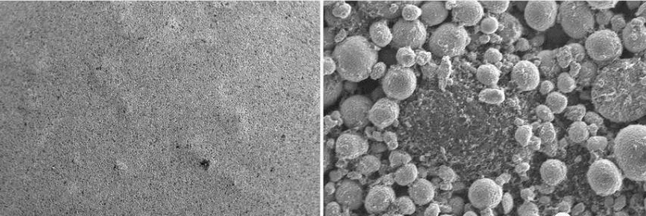
【1】 Bubble defects in the negative electrode coating of lithium-ion batteries

The negative electrode plate with bubbles in the left image and the 200x magnification of the scanning electron microscope in the right image. During the process of mixing, transportation, and coating, dust or long flocs and other foreign objects mix into the coating solution or fall onto the surface of the wet coating. The surface tension of the coating at this point is affected by external forces, causing changes in intermolecular forces, resulting in mild transfer of the slurry. After drying, circular marks are formed, with a thin center.
【2】 Pinhole
One is the generation of bubbles (stirring process, transportation process, coating process); The pinhole defect caused by bubbles is relatively easy to understand. Bubbles in the wet film migrate from the inner layer to the surface of the film, and rupture on the surface to form a pinhole defect. Bubbles mainly come from poor fluidity, poor leveling, and poor release of bubbles during mixing, liquid transportation, and coating processes.
Possible causes: Foreign objects or large particles getting stuck in the narrow gap or coating gap, poor substrate quality, causing foreign objects blocking the coating gap between the coating roller and the back roller, and damage to the mold lip.
【4】 Thick edge
The reason for the formation of thick edges is driven by the surface tension of the slurry, which causes the slurry to migrate towards the uncoated edge of the electrode, forming thick edges after drying.
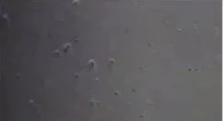
【5】 Aggregated particles on the negative electrode surface

Formula: Spherical graphite+SUPER C65+CMC+distilled water
Macro morphology of polarizers with two different stirring processes: smooth surface (left) and presence of a large number of small particles on the surface (right)

Formula: Spherical graphite+SUPER C65+CMC/SBR+Distilled water
Enlarged morphology of small particles on the surface of the electrode (a and b): Aggregates of conductive agents, not completely dispersed.
Enlarged morphology of smooth surface polarizers: The conductive agent is fully dispersed and evenly distributed.
Formula: NCA+acetylene black+PVDF+NMP
During the mixing process, the environmental humidity is too high, causing the slurry to become jelly like, the conductive agent is not completely dispersed, and there are a large number of particles on the surface of the polarizer after rolling.
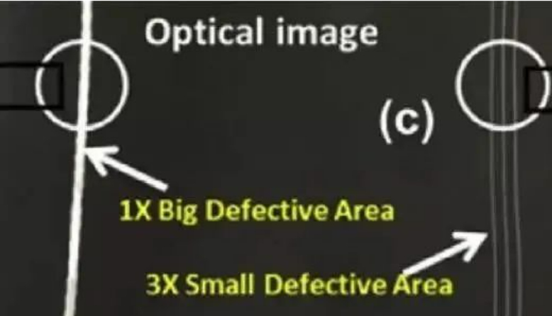
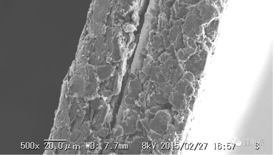
【7】 Cracks in water system polar plates
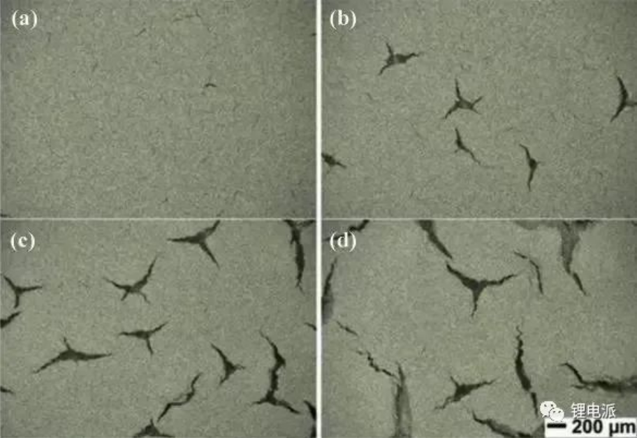
Formula: NMC532/carbon black/binder=90/5/5 wt%, water/isopropanol (IPA) solvent
Optical photos of surface cracks on polarizers, with coating densities of (a) 15 mg/cm2, (b) 17.5 mg/cm2, (c) 20 mg/cm2, and (d) 25 mg/cm2, respectively. Thick polarizers are more prone to cracks.

Formula: flake graphite+SP+CMC/SBR+distilled water
The presence of pollutant particles on the surface of the foil results in a low surface tension area of the wet film on the surface of the particles. The liquid film emits and migrates towards the periphery of the particles, forming shrinkage point defects.

Formula: NMC532+SP+PVdF+NMP
Narrow seam extrusion coating, with large particles on the cutting edge causing foil leakage and scratches on the surface of the electrode.
Formula: NCA+SP+PVdF+NMP
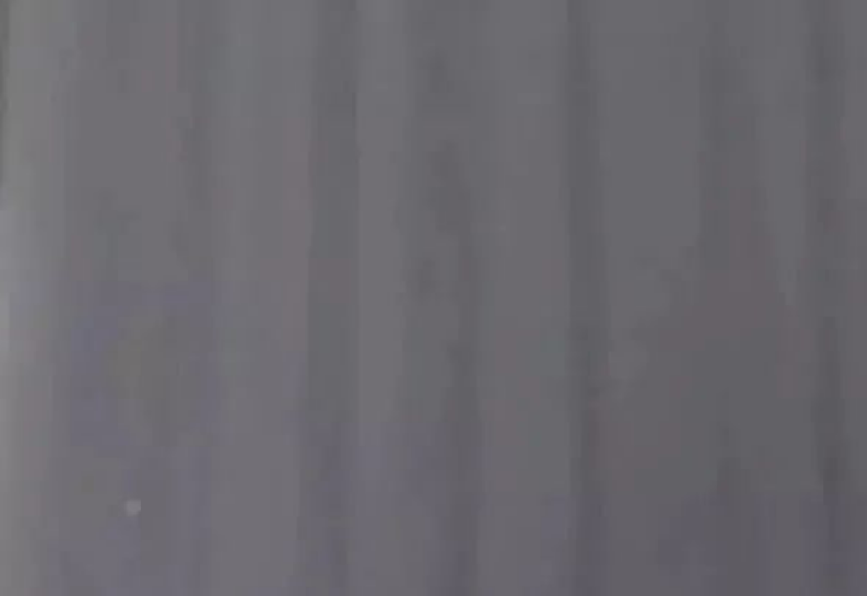
In the later stage of transfer coating, the water absorption viscosity of the slurry increases, approaching the upper limit of the coating window during coating, resulting in poor leveling of the slurry and the formation of vertical stripes.

Formula: flake graphite+SP+CMC/SBR+distilled water
During coating, the middle area of the polarizer is not completely dry, and during rolling, the coating migrates, forming strip-shaped cracks.
The phenomenon of thick edges formed by coating, roller pressing, and wrinkling of the coating edges
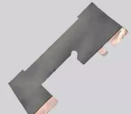
【13】 Negative electrode cutting coating detached from foil
Formula: natural graphite+acetylene black+CMC/SBR+distilled water, active substance ratio 96%
When the polar disc is cut, the coating and foil detach.
During the cutting of the positive electrode disc, unstable tension control leads to the formation of foil burrs during secondary cutting.
【15】 Polar slice cutting wave edge

During the cutting of the negative electrode disc, due to inappropriate overlap and pressure of the cutting blades, wave edges and coating detachment of the incision are formed.
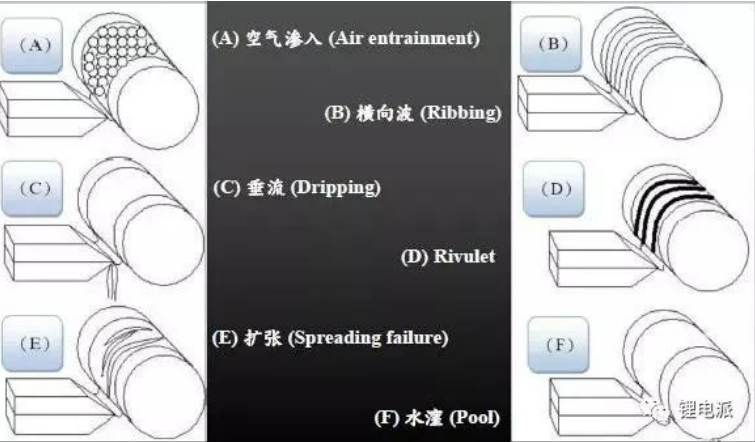
【16】 Other common coating defects include air infiltration, lateral waves, sagging, Rivulet, expansion, water damage, etc
Defects may occur in any processing stage: coating preparation, substrate production, substrate operation, coating area, drying area, cutting, slitting, rolling process, etc. What is the general logical method for solving defects?
1.During the process from pilot production to production, it is necessary to optimize the product formula, coating and drying process, and find a relatively good or wide process window.
2. Use some quality control methods and statistical tools (SPC) to control the quality of products. By monitoring and controlling the stable coating thickness online, or using a visual appearance inspection system (Visual System) to check for defects on the coating surface.
3. When product defects occur, adjust the process in a timely manner to avoid repeated defects.
05
Uniformity of coating
The so-called uniformity of coating refers to the consistency of the distribution of coating thickness or adhesive amount within the coating area. The better the consistency of coating thickness or adhesive amount, the better the uniformity of coating, and vice versa. There is no unified measurement index for coating uniformity, which can be measured by the deviation or percentage deviation of the coating thickness or adhesive amount at each point in a certain area relative to the average coating thickness or adhesive amount in that area, or by the difference between the maximum and minimum coating thickness or adhesive amount in a certain area. The coating thickness is usually expressed in µ m.
The uniformity of coating is used to evaluate the overall coating condition of an area. But in actual production, we usually care more about the uniformity in both the horizontal and vertical directions of the substrate. The so-called horizontal uniformity refers to the uniformity of the coating width direction (or machine's horizontal direction). The so-called longitudinal uniformity refers to the uniformity in the direction of coating length (or substrate travel direction).
There are significant differences in the size, influencing factors, and control methods of horizontal and vertical glue application errors. In general, the larger the width of the substrate (or coating), the more difficult it is to control the lateral uniformity. Based on years of practical experience in coating online, when the substrate width is below 800mm, lateral uniformity is usually easily guaranteed; When the width of the substrate is between 1300-1800mm, the lateral uniformity can often be well controlled, but there is a certain difficulty and a considerable level of professionalism is required; When the substrate width is above 2000mm, controlling the lateral uniformity is very difficult, and only a few manufacturers can handle it well. When the production batch (i.e. coating length) increases, longitudinal uniformity may become a greater difficulty or challenge than transverse uniformity.